Make shift lathe to reduce the head tap some tread end fit ballbearing....going to convert my mill to cnc.....well going to try
And have taken of the springload to the mill head and made it a counter balance system
Bought the steppers and driver and tested if it works....and yes it does
Printed prototype motormount and followed up with aluminium

Find centre with some string
Lineup the mill
I also need a spacing block to suit the coupling beween leadscrew and motor.
This will need access for thightning the scrubscrew on the coupler. The distance is about 30mm that i want to keep clean during operation....I figured using my trusty wombot and print a box i can fill with resin for strength and it's purpose is to hold a skateboard bearing and breach the distance for the coupler
Had some curling of the plate during print so used more support than needed as you can see
Nice, now lets print the next one overnigh
Uuuuhhhh thats not the box your looking for.....i think the tape from the heating block has come free and got in the way of the plastic....oops, the tape is not really needed so head it up and that piece of "art" came right of...... Hit print and now i have 2 boxes ready for resin, nothing fancy just diggers from bunnings.
Outside job....that stuff smells.....bad
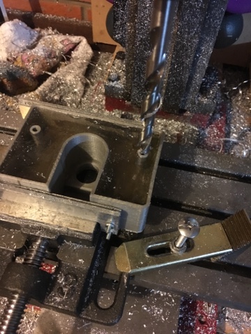
Drill out the placeholder for the bolt location above and line up the motormount for counter sinking picture below
Made some other aluminium plates for fixing back to the table later on
Just quick mock up
Cut the tread and mounthing x and y are done
Yay my tap arrived
And so i made a quick and dirty delrin nut to test how thight it is.
Runs really smooth so ill skip on backlash because i'm not noticing any yet.
Now 3d something up for a cover plate to keep the chips out of the coupler space
The first nut was way of centre so i printed a block to pin point the middle and at the same time cut the right length
Ones cut and drilled out an tapped it needs to able to be fixed to the compound table.....after a few goes i finnally managed to get something small enough yet strong enough. The print will be fine and if not i'll replace bits with aluminium.
Here it is mid print (nice and solid
The fix screw and capend screws will only just miss each other, so little space under that table
In the meantime some rewiring because i found a old stereo
Still need to protect the wires on the motors and figure out Z direction...the leadnut housing broke so i came up with a sideways solution and used the same for z direction, made a mounting block for motor that i fixed to a new small column.
The nut plate and the new column are fixed to the mill by using the existing bolt holes where the spring used to be
Lets wire up and give it a spin.
That worked, under load my axis connection to the motor had some trouble so had to put in some grub screw for more grip
....more testing
I am using the shapeoko arduino flashing so thought it was fitting for the "hallo world"
Enough testing lets give it a good workout
10mm aluminium BOOOYYaaaa so happy
the skateboard bearing is completely flat and is now replaced with a proper "thrust" bearing.....will update soon


No comments:
Post a Comment